

Custom Gauge Lighting With L.E.D.'s
Inspired by Naskie18
Modded, Written, and Edited by ZachSettle
Updated: 10/06/2011
Changelog:
03/26/13
*Contact me directly with any questions at Zach.Settle[AT]gmail.com as I don't visit ColoradoFans too often anymore.
03/06/2012
*I've since sold my first colorado and my second, but I am still available for questions. Feel free to message me.
*Updated with some photos from my second LED swap on my automatic Xtreme.
*Spell-checked.
10/06/2011
*I'm still around and available for any questions you guys might have.
*Added two website I used to purchase LEDs from. Both are outstanding. Oznium.com has a larger availability.
*Condensed how-to
Disclaimer: This is How-To. This is a no warranty assoicated with this. If you break something or destroy your gauge cluster that is your own fault. By continuing with this How to you are accepting this responsibilty and cannot blame me at all.
![Image]()
Preparation time: 20 minutes
Project time: 70 minutes
Cure time: 0 minutes
Total time: 1 hour, 30 minutes
Things You Need:
Solder (The thinner the better)
25w Soldering Iron (I used the yellow pencil kind)
(6) 3mm L.E.Ds
- Places to purchase LEDs:
Modsthatglow.com
Oznium.com
Torex 10 screwdriver (T10)
Flat-tip screwdriver
Socket-driver and extension
7mm Socket
Sandpaper (any grit will work)
Needle nose pliers
Things to make your life easier:
An old t-shirt
A friend or "Helping Hands"
Fuse puller, Tweezers, or screw retriever
Magnetic-tipped socket driver
Dremel with sanding disk
**Resistors are not required. The stock bezel is correctly wired for LEDs bulb from the factory.
Preparations:
P-1. Sort out the L.E.Ds you want to use. You will need six to do all of the gauges.
P-2. Using your sand paper, sand down the L.E.D as small as you can without exposing the elements inside. You want to focus on the the top of the LED, but you can sand the sides as well if you desire.
Note: You can use a dremel with a sanding disk and this will cut down your preparation time greatly.
P-3. Clip your leads as small as possible on the L.E.D. with the pliers. Leave about 1/8" of an inch. (.125")
P-4. Using your pliers again, bend the leads opposite of each other, creating somewhat of a backwards Z shape with the leads. (See Figure)
![Image]()
Removing Your Gauge's Bezel:
1. Pull in the areas identified in the following figure. There is a lip that you can feel with your fingertips. Grab a hold of that and pull back.
Note: When returning the bezel to the gauge ensure you start from the bottom and place the lip of the bezel behind the dash. Take a look at your bezel and you'll see what I mean. Also, ensure the Trip Meter Needle is not obstructed.
2. The bezel is held in place by four (4) clips.
Note: If a clip does not stay attached to the bezel when you pull it out and remains in the dash DO NOT try to force it out! Instead push it through to the other side and fish it out underneath the steering column. This is the easiest way to do this and prevents you from breaking your clips.
Removing Your Gauge Cluster:
1. As identified in the figure there are four (4) hexagonal bolts. Remove these with a counter clockwise turn of your socket driver. You will need to use your socket driver's extention to reach the bolts.
2. Once the bolts have been removed, pull the gauge back, up, and out over the steering wheel. Do not pull too hard, it's still connected to your truck's harness. (See Figure)
3a. Rotate the gauge cluster so that you have access to the clip.
3b. While pressing down on the three bumps on top of the clip, simultaneously pull the bracket around the clip downward. (See Video)
3c. This should eject the harness from the back of cluster and allow you to remove the cluster from the confines of the vehicle.

Accessing the Printed Circut Board (PCB):
1. Flip the cluster over and place it on something soft like a fleece blanket in order to prevent scratching the plastic covering.
2. Using your T10 driver, remove the eight [8] torex screws with counter clockwise turns. (See Figure)
![Image]()
3. The cluster should now come apart into three parts.
Note: Be careful not to bend or break the trip counter needle here.
5. With your flat-tip screwdriver slide it underneath the backside of the needle and slowly pry up. (See Figure)
![Image]()
Note: More force than you think necessary will be applied. They are stuck on there pretty good.
Tip: I used an old t-shirt and wrapped the tip of the screwdriver in it to prevent scratch the gauge faces.
6. If you are afraid of breaking your needles, start with least important gauge and work your way up. For me I did them in the following order: Temperature, Gas, RPM, and then Speed.
Note: Try not to move the needles. They are calibrated correctly and are pain to fix. DON'T WORRY if you move them. I'll teach you how to calibrate them later on in this How-To.
7. Once you have taken off the needles, the PCB should slide right off the gauge faces.
8. Set your needles aside and bask in the glory of Chevrolet engineering. :roll:
Identifying the LEDs to change:
![Image]()
On the lower left hand side you have
a. DRL Indicator
b. Airbags
c. ABS
d. Check Engine Light``
e. Seat belt
f. Battery
On the lower right hand side you have
g. Emergency Brake
h. Cruise Control
i. Shift Light
j. Security Light
k. Oil Pressure
l. On the bottom row are the LEDs that illuminate your H.U.D.
In the middle you have
m. On the right: two (2) LEDs for Speed
n. On the left: two (2) LEDs for RPM
At the top you have
o. Gas
p. Temp
q. Right Turn Signal
r. Left Turn Signal
s. High Beam Indicator
Note: You can change out all of the LEDs but I do not recommend it. If you would like to change the color of your indicator lights and turn signals simply remove the plastic film over the cutout on the gauge face and replace with the color of your choice.
Desoldering the factory LEDs:
1. Heat up your soldering iron.
2. Located the LED you want to remove.
3a. Starting on a single side, heat up the solder by touching it with the tip of your iron.
3b. Slowly pull up on the LED, you will feel it budge slightly.
3c. On the opposite side of the LED, heat the solder and pull up on the LED. It should come off.
Note: Using a screw retriever, needle nose pliers, fuse puller, or tweezers is much easier than your fingers. And less painful.
Soldering the replacement LEDs:
Assuming you were able to desolder the LEDs ok, you can now move on to soldering the replacement LEDs.
1. Adjust the new LED so that polarity matches up with the figure.
2. Solder each lead, ensuring you don't solder the leads together.
3. Repeat with each LED you want to change out.
4. Here's a shot of the "Helping Hands" and the "Helping Hands" in action.
![Image]()
![Image]()
Note: The temperature LED has a reversed polarity. Make sure that you solder your LEDs the correct way. The negative lead should be on the top.
Note: For the LEDS that illuminate the information center, they point directly up. For these it essential you bend the LED's legs in the same direction. See photo for reference:
![Image]()
Operation Test
1. Take your finished worked to your Colorado, holding the PCB by the edges.
2. Plug the harness back in. You should hear a click and a winding sound. This is ok. Your cluster is being powered on and your truck's ECM is sending information to be displayed in the information center.
3. Turn your headlights on by turning the headlight wheel to the right one or two clicks.
4. Does everything light up?
If Not - Check your connections, check your polarities, and check that you haven't soldered two leads together.
Reminder: All of the LEDs have their positive polarity marked with a "K" next to them on my 2007 board out of my Xtreme. This made things much easier. On my 2005 board, there were no markings. Wiring the LEDs in backwards does not harm the PCB. They will simple fail to illuminate.
If They Do - Pat yourself on your back and move on to the next step.
Assemble the Gauge Cluster
1. Align the gauge face and the PCB.
2. Ensure your new LEDs are not too tall and prevent the needles' post from sticking out on the gauge face. If they do you can either go back and shorten your leads on your LED or do the following.
3. Once you have gauge face and PCB aligned, place the needles as close to zero as you can and gently press the needle back down. "Zero" being their calibrated starting point, not the actual number.
4. Once you have placed them on the post check their tension. Do they slide easily or is there some resistance?
5. If there is some resistance chances are that the needles won't move once the vehicle is started. The only way to tell is to fire her up and drive her around the block (or down the street and back).
Note: To alleviate this problem, try not to press down to hard on the needle. Place it on the post and only press it down only a little bit. It worked for me.
Return the Gauge Cluster to the Dashboard
1. With the needles in place and zero'ed in, go ahead and place the gauge face back inside the plastic cover and return the black plastic back panel on top of that.
2. Screw all eight [8] torx in clockwise.
3. Return the gauge to the harness and screw all (4) four bolts clockwise.
4. Snap the gauge bezel back in place, paying attention to the bottom. Ensure the bottom slides behind the dash before snapping in the top.
DONE!
----------------
Project & durability update: (5 years later)
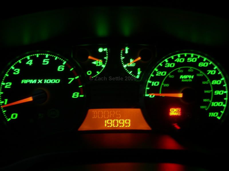
After having the green LEDs in for a few years I noticed that two on the left side of the gauge cluster would becoming dimly lit or would black out altogether. From my understanding this was due to a bad connection from the soldering breaking loose from the cluster's PCB, most likely from a cold solder. This is from rushing the process and not heating up the the entire solder past it's melting point.
On a happier note I traded in my '05 for an '07 Xtreme with an automatic transmission and will be updating the tutorial to reflect an automatic transmission gauge cluster.
Using a single color on the cluster prevents brighter colors of different shades from washing into each other. I was not impressed with using white on the information center. It caused the information center to display in purple.
![Image]()
Inspired by Naskie18
Modded, Written, and Edited by ZachSettle
Updated: 10/06/2011
Changelog:
03/26/13
*Contact me directly with any questions at Zach.Settle[AT]gmail.com as I don't visit ColoradoFans too often anymore.
03/06/2012
*I've since sold my first colorado and my second, but I am still available for questions. Feel free to message me.
*Updated with some photos from my second LED swap on my automatic Xtreme.
*Spell-checked.
10/06/2011
*I'm still around and available for any questions you guys might have.
*Added two website I used to purchase LEDs from. Both are outstanding. Oznium.com has a larger availability.
*Condensed how-to
Disclaimer: This is How-To. This is a no warranty assoicated with this. If you break something or destroy your gauge cluster that is your own fault. By continuing with this How to you are accepting this responsibilty and cannot blame me at all.
Preparation time: 20 minutes
Project time: 70 minutes
Cure time: 0 minutes
Total time: 1 hour, 30 minutes
Things You Need:
Solder (The thinner the better)
25w Soldering Iron (I used the yellow pencil kind)
(6) 3mm L.E.Ds
- Places to purchase LEDs:
Modsthatglow.com
Oznium.com
Torex 10 screwdriver (T10)
Flat-tip screwdriver
Socket-driver and extension
7mm Socket
Sandpaper (any grit will work)
Needle nose pliers
Things to make your life easier:
An old t-shirt
A friend or "Helping Hands"
Fuse puller, Tweezers, or screw retriever
Magnetic-tipped socket driver
Dremel with sanding disk
**Resistors are not required. The stock bezel is correctly wired for LEDs bulb from the factory.
Preparations:
P-1. Sort out the L.E.Ds you want to use. You will need six to do all of the gauges.
P-2. Using your sand paper, sand down the L.E.D as small as you can without exposing the elements inside. You want to focus on the the top of the LED, but you can sand the sides as well if you desire.
Note: You can use a dremel with a sanding disk and this will cut down your preparation time greatly.
P-3. Clip your leads as small as possible on the L.E.D. with the pliers. Leave about 1/8" of an inch. (.125")
P-4. Using your pliers again, bend the leads opposite of each other, creating somewhat of a backwards Z shape with the leads. (See Figure)

Removing Your Gauge's Bezel:
1. Pull in the areas identified in the following figure. There is a lip that you can feel with your fingertips. Grab a hold of that and pull back.
Note: When returning the bezel to the gauge ensure you start from the bottom and place the lip of the bezel behind the dash. Take a look at your bezel and you'll see what I mean. Also, ensure the Trip Meter Needle is not obstructed.
2. The bezel is held in place by four (4) clips.
Note: If a clip does not stay attached to the bezel when you pull it out and remains in the dash DO NOT try to force it out! Instead push it through to the other side and fish it out underneath the steering column. This is the easiest way to do this and prevents you from breaking your clips.
Removing Your Gauge Cluster:
1. As identified in the figure there are four (4) hexagonal bolts. Remove these with a counter clockwise turn of your socket driver. You will need to use your socket driver's extention to reach the bolts.
2. Once the bolts have been removed, pull the gauge back, up, and out over the steering wheel. Do not pull too hard, it's still connected to your truck's harness. (See Figure)
3a. Rotate the gauge cluster so that you have access to the clip.
3b. While pressing down on the three bumps on top of the clip, simultaneously pull the bracket around the clip downward. (See Video)
3c. This should eject the harness from the back of cluster and allow you to remove the cluster from the confines of the vehicle.
Accessing the Printed Circut Board (PCB):
1. Flip the cluster over and place it on something soft like a fleece blanket in order to prevent scratching the plastic covering.
2. Using your T10 driver, remove the eight [8] torex screws with counter clockwise turns. (See Figure)

3. The cluster should now come apart into three parts.
- a. The black protective spacer
b. The gauges/PCB
c. The plastic covering.
Note: Be careful not to bend or break the trip counter needle here.
5. With your flat-tip screwdriver slide it underneath the backside of the needle and slowly pry up. (See Figure)

Note: More force than you think necessary will be applied. They are stuck on there pretty good.
Tip: I used an old t-shirt and wrapped the tip of the screwdriver in it to prevent scratch the gauge faces.
6. If you are afraid of breaking your needles, start with least important gauge and work your way up. For me I did them in the following order: Temperature, Gas, RPM, and then Speed.
Note: Try not to move the needles. They are calibrated correctly and are pain to fix. DON'T WORRY if you move them. I'll teach you how to calibrate them later on in this How-To.
7. Once you have taken off the needles, the PCB should slide right off the gauge faces.
8. Set your needles aside and bask in the glory of Chevrolet engineering. :roll:
Identifying the LEDs to change:

On the lower left hand side you have
a. DRL Indicator
b. Airbags
c. ABS
d. Check Engine Light``
e. Seat belt
f. Battery
On the lower right hand side you have
g. Emergency Brake
h. Cruise Control
i. Shift Light
j. Security Light
k. Oil Pressure
l. On the bottom row are the LEDs that illuminate your H.U.D.
In the middle you have
m. On the right: two (2) LEDs for Speed
n. On the left: two (2) LEDs for RPM
At the top you have
o. Gas
p. Temp
q. Right Turn Signal
r. Left Turn Signal
s. High Beam Indicator
Note: You can change out all of the LEDs but I do not recommend it. If you would like to change the color of your indicator lights and turn signals simply remove the plastic film over the cutout on the gauge face and replace with the color of your choice.
Desoldering the factory LEDs:
1. Heat up your soldering iron.
2. Located the LED you want to remove.
3a. Starting on a single side, heat up the solder by touching it with the tip of your iron.
3b. Slowly pull up on the LED, you will feel it budge slightly.
3c. On the opposite side of the LED, heat the solder and pull up on the LED. It should come off.
Note: Using a screw retriever, needle nose pliers, fuse puller, or tweezers is much easier than your fingers. And less painful.
Soldering the replacement LEDs:
Assuming you were able to desolder the LEDs ok, you can now move on to soldering the replacement LEDs.
1. Adjust the new LED so that polarity matches up with the figure.
2. Solder each lead, ensuring you don't solder the leads together.
3. Repeat with each LED you want to change out.
4. Here's a shot of the "Helping Hands" and the "Helping Hands" in action.


Note: The temperature LED has a reversed polarity. Make sure that you solder your LEDs the correct way. The negative lead should be on the top.
Note: For the LEDS that illuminate the information center, they point directly up. For these it essential you bend the LED's legs in the same direction. See photo for reference:

Operation Test
1. Take your finished worked to your Colorado, holding the PCB by the edges.
2. Plug the harness back in. You should hear a click and a winding sound. This is ok. Your cluster is being powered on and your truck's ECM is sending information to be displayed in the information center.
3. Turn your headlights on by turning the headlight wheel to the right one or two clicks.
4. Does everything light up?
If Not - Check your connections, check your polarities, and check that you haven't soldered two leads together.
Reminder: All of the LEDs have their positive polarity marked with a "K" next to them on my 2007 board out of my Xtreme. This made things much easier. On my 2005 board, there were no markings. Wiring the LEDs in backwards does not harm the PCB. They will simple fail to illuminate.
If They Do - Pat yourself on your back and move on to the next step.
Assemble the Gauge Cluster
1. Align the gauge face and the PCB.
2. Ensure your new LEDs are not too tall and prevent the needles' post from sticking out on the gauge face. If they do you can either go back and shorten your leads on your LED or do the following.
3. Once you have gauge face and PCB aligned, place the needles as close to zero as you can and gently press the needle back down. "Zero" being their calibrated starting point, not the actual number.
4. Once you have placed them on the post check their tension. Do they slide easily or is there some resistance?
5. If there is some resistance chances are that the needles won't move once the vehicle is started. The only way to tell is to fire her up and drive her around the block (or down the street and back).
Note: To alleviate this problem, try not to press down to hard on the needle. Place it on the post and only press it down only a little bit. It worked for me.
Return the Gauge Cluster to the Dashboard
1. With the needles in place and zero'ed in, go ahead and place the gauge face back inside the plastic cover and return the black plastic back panel on top of that.
2. Screw all eight [8] torx in clockwise.
3. Return the gauge to the harness and screw all (4) four bolts clockwise.
4. Snap the gauge bezel back in place, paying attention to the bottom. Ensure the bottom slides behind the dash before snapping in the top.
DONE!
----------------
Project & durability update: (5 years later)
After having the green LEDs in for a few years I noticed that two on the left side of the gauge cluster would becoming dimly lit or would black out altogether. From my understanding this was due to a bad connection from the soldering breaking loose from the cluster's PCB, most likely from a cold solder. This is from rushing the process and not heating up the the entire solder past it's melting point.
On a happier note I traded in my '05 for an '07 Xtreme with an automatic transmission and will be updating the tutorial to reflect an automatic transmission gauge cluster.
Using a single color on the cluster prevents brighter colors of different shades from washing into each other. I was not impressed with using white on the information center. It caused the information center to display in purple.


